What Is a Cut-to-Length Line for Transformer Cores? How a CTL Line Works, Station by Station
A cut-to-length (CTL) line turns coils of grain-oriented silicon steel into finished core laminations. This guide walks through every station on the line, what each one does to the strip, and which numbers on a datasheet actually matter.
A cut-to-length line (often shortened to CTL line, and in some markets called a cross-cutting line or transverse shearing line) is the machine that turns a coil of grain-oriented silicon steel into the individual laminations that are stacked into a transformer core. The coil goes in one end as a continuous strip; finished yoke and limb pieces come out the other end, already cut to length, mitred at 45°, notched and, on most lines, sorted onto stacking tables in the order the core builder needs them.
If you are specifying your first line or comparing offers, it helps to know what happens at each station, because almost every line in the market is built from the same sequence of operations. The differences are in how fast each station works, how accurately, and how much of the handling around the line is automated.
What the line has to produce
A three-phase, three-limb stacked core is built from a handful of lamination shapes: two outer limbs with 45° mitred ends, a centre limb with pointed (V) ends, and two yokes with mitred ends and a V-notch in the middle where the centre limb sits. In a step-lap core the joint position is shifted by a small step from one layer group to the next, so the same shape is cut in several slightly different lengths and the line has to cycle through those lengths automatically.
Every station on a CTL line exists to make one of those features: the shear makes the 45° and 90° ends, the V-notch punch makes the notch and the pointed tips, the hole punch makes bolt holes on designs that still use them, and the feed system positions the strip to the right length before each cut.
The stations, in order
1. Decoiler
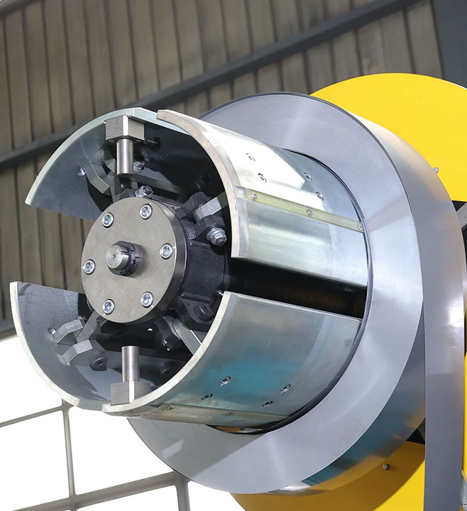
The coil sits on a hydraulic expanding mandrel that grips the coil bore and pays the strip out under controlled tension. Lines are offered with two to four decoiler heads so that the next coil, or a strip of a different width, can be loaded while the line is running. Coil weight capacity matters more than it looks: on a one-metre-class line the decoiler carries coils of around five tonnes, and the mandrel, brake and loading car are sized accordingly.
2. Feed and guiding
Servo-driven feed rollers move the strip forward by the exact lamination length and stop it for each cut on a standard line, or run it continuously on a high-speed line where the tooling moves with the strip. Edge guides keep the strip centred so that the notch and the mitred ends land in the same place on every piece. Feed accuracy is what sets the length tolerance of the finished lamination, which is why the feed axis is a servo axis and not a simple motor drive.
3. V-notch punch
A servo-driven punching station cuts the V-shaped notch that receives the centre limb, and, combined with the shear, produces the pointed ends of the centre limb laminations. Lines are configured with one or two V stations. The second station is specified when the two yokes of a core have different widths or when the core is going to be stacked automatically and needs symmetric joints; we cover the sizing rule in the article on step-lap cutting and V-notches.
4. Hole punch (optional)
Older core designs and some larger cores are clamped through bolt holes in the laminations. A hole punching station, or several, cuts these holes in the same pass. Modern distribution transformer cores are usually clamped without holes, so the station is an option rather than a standard, and a line can be ordered with zero to four hole punches.
5. Mitre shear
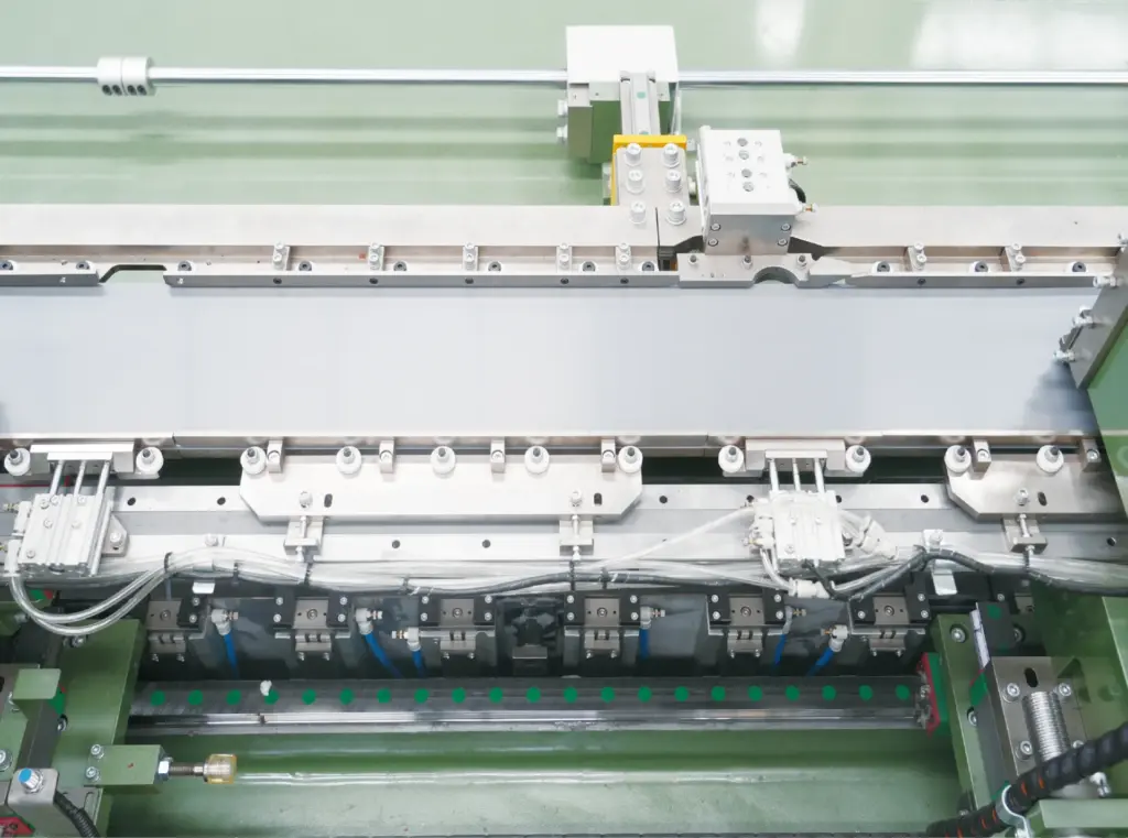
The shear is the heart of the line. It rotates between 45° and 90° so that mitred and straight cuts can be made in the same pass without changing tooling. Cut quality here decides burr height, and angular accuracy of the shear decides how well the mitred joints of the core close up. Two shear stations let the line make both cuts of a lamination without a return stroke on the rotation.
6. Sorting and stacking tables
Finished laminations are conveyed off the shear and dropped onto stacking tables, sorted by piece type so that the stacks arrive at the core assembly area in build order. Tables are configured as 1+1, 3+3 or 5+5 pairs; the second table of each pair fills while the first is being taken away by forklift. High-speed lines use an extended sorting chain because the pieces arrive faster. Lines can also feed a core-stacking machine directly, which is the idea behind a cut-and-stack combined line.
7. Control system
A PLC with servo drives coordinates the feed length, the punch positions and the shear angle for each piece of the program. The program itself is the list of pieces for a core: shape, length, notch position, quantity and stacking order. On SREE lines the program can be entered at the operator terminal or generated from the lamination drawing by the optional PLS terminal, which reads the drawing and produces the cutting program automatically.
Reading a cut-to-length line datasheet
Every supplier’s datasheet lists the same handful of numbers. This is what each one means in practice.
| Parameter | What it tells you | Typical SREE figures |
|---|---|---|
| Width class / strip width | The widest lamination the line can cut. Choose by the widest piece in your core designs, usually the centre limb or the yoke. | Six classes from 200 to 1000 mm; see how to choose the width class |
| Толщина полосы | The range of silicon steel gauges the feed and tooling are set up for. | 0.18 to 0.35 mm as standard; 0.15 mm on request |
| Длина пластины | Shortest and longest piece the line can cut in one program. | Depends on class; a 1000-class line covers 600 to 5,000 mm |
| Feed speed | Strip speed through the line. Peak speed is not shift output; see peak speed vs real output. | Up to 210 m/min rated on standard lines; 240 m/min peak on high-speed lines |
| Допуск по длине | Allowed deviation of the cut length, quoted per reference length. | ±0.2 mm per 2 m |
| Допуск по углу | Deviation of the 45° mitre from nominal. Decides how well joints close. | ±0.02° |
| Burr height | Sharp edge left by the shear. Affects interlaminar insulation and stacking factor. | ≤0,02 мм |
| Installed power | Sum of drives and hydraulics. Varies with the number of stations, not only with class. | Roughly 40 to 95 kW depending on configuration |
Tolerances only mean something together with the conditions under which they were measured. When comparing offers, ask each supplier how the angle and length figures were tested and on which material; we discuss what to ask in cutting tolerances that matter for transformer cores.
Standard and high-speed lines
SREE builds two families of CTL line. The standard line feeds step by step: the strip stops, the stations act, the strip moves on. The high-speed line keeps the strip moving and the punching and shearing stations travel with it, which removes the stop-start cycle and raises output for the same strip speed. Which one pays off depends on monthly tonnage and how often you change core types; this comparison gives the rule of thumb we use when sizing.
How SREE model numbers are built
Our model codes describe the line configuration directly. SRHJ400-223G, for example, reads as follows: SRHJ is the cut-to-length series, 400 is the width class in millimetres, 2-2-3 is the number of shears, V-notch punches and hole punches, and G marks the high-speed version (B marks the standard NC version). A cut-and-stack combined line uses the SRJD prefix, a slitting line SRZJ, and a stand-alone stacking line SRDZ.
Frequently asked questions
Is a cut-to-length line the same as a cross-cutting line?
Yes. Cut-to-length line, CTL line, cross-cutting line and transverse shearing line all describe the same machine: it cuts across the strip to length, as opposed to a slitting line, which cuts along the strip to width.
Can one line cut all the pieces of a core?
Yes, that is the point of the line. Outer limbs, centre limb and yokes for one core are cut in one program from strips of the required widths, with the step-lap length variations included, and delivered sorted onto the stacking tables.
Does the line need a slitting line in front of it?
Only if you buy master coils and slit them yourself. Many core shops buy pre-slit strip from the steel mill or a service centre and run the CTL line directly from those coils.
How is the cutting program created?
From the lamination drawing. The operator enters piece shapes, lengths and quantities at the terminal, or the optional PLS terminal reads the drawing file and generates the program.
Sizing a line for your core shop?
Send strip widths, thickness and monthly tonnage. You get a line proposal with knife layout and floor plan, or use the online selector to narrow the series first.